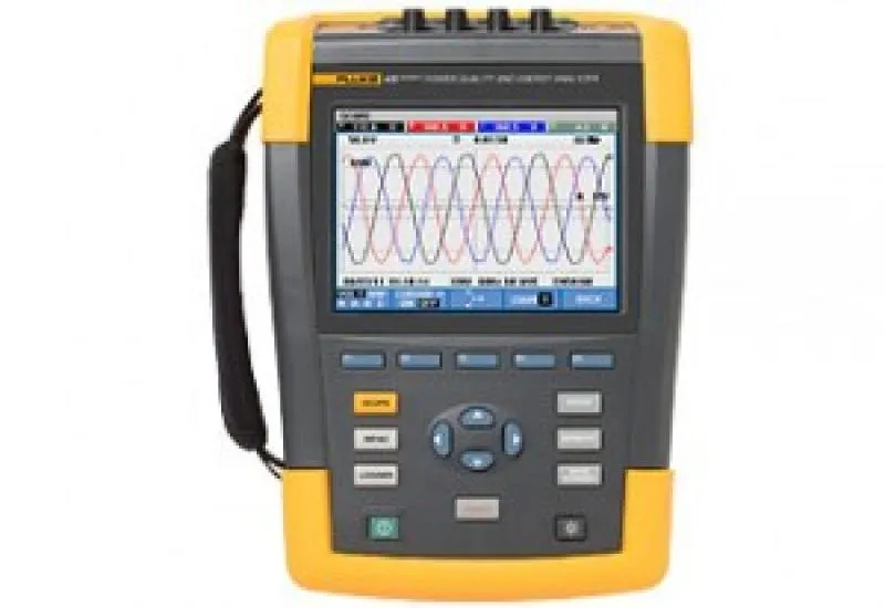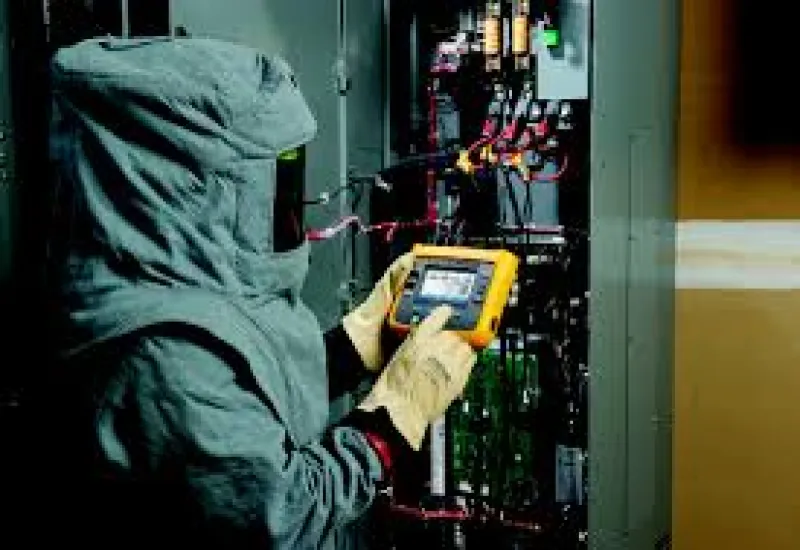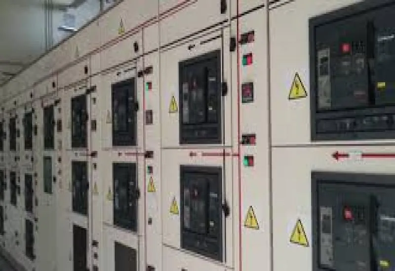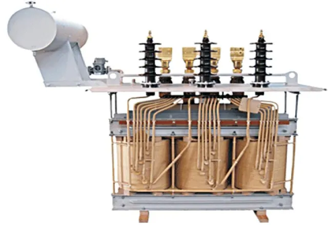
We have specialized equipment for testing current transformers (CTs) in substations in Monterrey, applying NMX‑J‑169‑ANCE‑2015, NMX‑J‑116‑ANCE‑2017 and IEC 60076
Equipment for oil analysis, ductor (low-resistance) testing, and insulation power factor testing.
Transformation ratio measurement of single-phase and three-phase transformers.
Phase deviation between the high-voltage and low-voltage windings.
Excitation current when measuring the transformation ratio.
Winding resistance measurement of single-phase and three-phase transformers.
TTR transformation ratio tests according to the IEEE C57.12.70 standard. We are members of the IEEE and the DEIS (Dielectric and Electrical Insulation Society) #94801861.
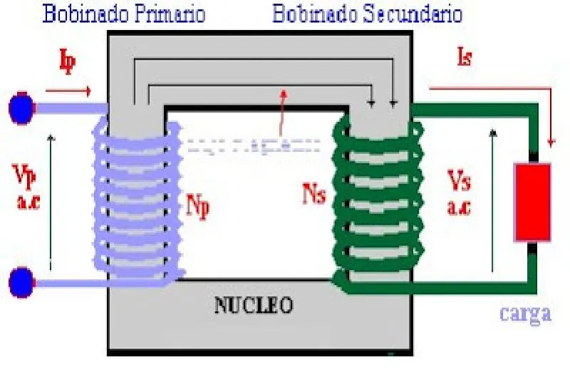
For CTs (current transformers) in substations, we can perform several tests that are critical to the correct operation of metering and relay circuits.
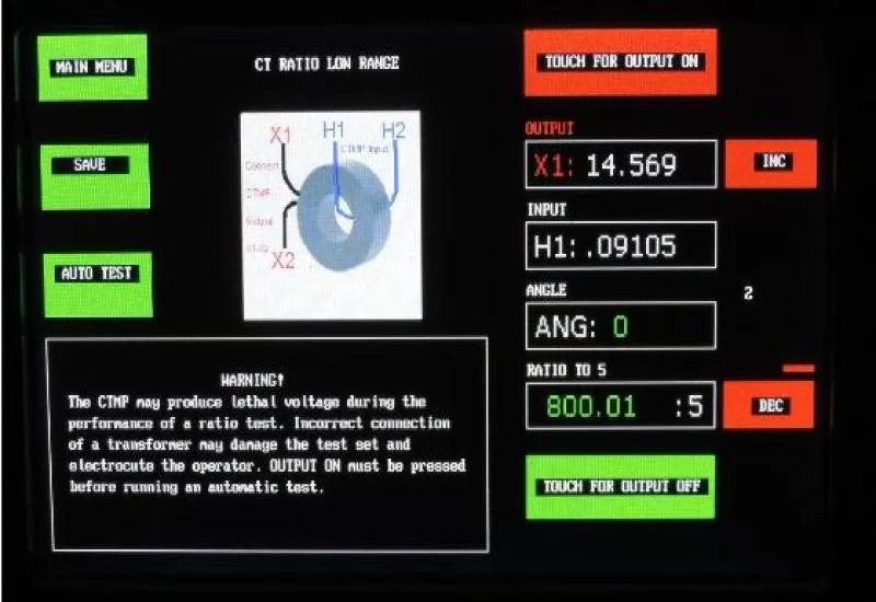
1) Ratio and polarity test of current and potential transformers: an incorrect ratio will result in financial loss due to incorrect kWh values or, in the case of protective relays, a failure of the relay to respond properly to a fault. An incorrect polarity will cause a kWh meter to run backward or a protective relay to malfunction. The relay may trip on a fault outside its zone and fail to trip for a fault in the protected apparatus. This test is necessary both during initial commissioning and as a periodic maintenance activity to identify defective equipment. You can use any image from my site that you like if that helps you.
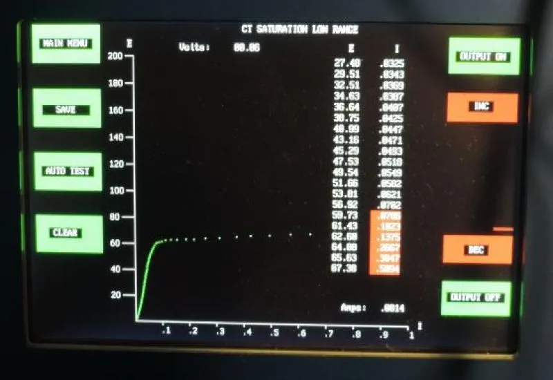
2) Current transformer saturation test:
This essential test establishes the ability of a CT to produce current in the proper ratio in the presence of its connected burden. If the burden, that is, the impedance of the secondary wiring, the meters and the relays, is (for example) 2 ohms and the secondary fault current is 100 amperes, the CT will have to produce 200 V. Therefore, you would want it to saturate at twice that level to avoid saturation in the presence of DC offset.
3) In-service test:
The phase angle and amplitude meter is a special test that allows connection to a test switch while the circuit is energized to verify that the expected current flows in the expected direction. This check is a test superimposed on the other tests.
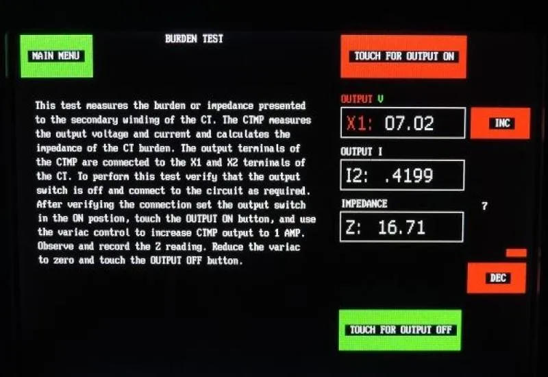
4) Secondary injection and burden test: the purpose of the burden test is to drive current and measure the impedance of the CT secondary circuit. The analyzer performs this test and gives you a direct burden value. Secondary injection allows you to inject current and read the amplitude and phase angle at a connected meter or relay. Simply measuring the current is not enough, because the wires may be crossed and the current may be 180 degrees out of phase during operation. If you do not want your relays to trip because of a fault out on the street, our equipment will verify your system so that does not happen.
In general, since the test set can save the data to a flash drive, it provides better data integrity, with no transcription errors on random scraps of paper.
The Ammo Can Meter is a more complete version of the phase angle meter (we use equipment with a new and improved measurement system) and measures the angle between two voltages as well as harmonic distortion.
We have MOT sources up to 2000 amperes. A high-current test set is needed to test and program ground-fault devices and circuit breakers. A ground-fault test is very common in substations, since a 480-volt service above a certain current requires ground-fault tripping. It must also be tested periodically. Another example is if you have a 200 A molded-case circuit breaker and you need to verify the trip time at 300%. This test set lets you apply 600 amperes and test the actual trip time.
 |
 |
|
 |
|
Analysis and measurement in electrical networks Measurement equipment used for line studies: Likewise, each recommendation will be aimed at optimally solving each problem, whether by correcting the electrical installation or by implementing protective equipment |
|