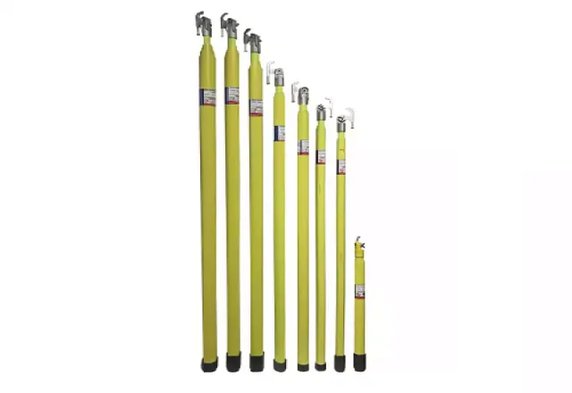
We perform electrical tests on grounding clamps with a micro-ohmmeter to determine the resistance of the conductor and clamps in accordance with the ASTM F2249-03 standard.
Scope of the test methods:
The specifications describe the in-service inspection and electrical testing of temporary grounding jumpers.
The test procedures in this specification provide an objective means of determining whether a grounding jumper
assembly meets the minimum electrical specifications.
Mechanical damage, other than broken strands, may not significantly affect cable resistance. Close
manual and visual inspection is required to detect some types of mechanical damage.
Retest the grounding jumper assembly after performing any maintenance to ensure its integrity.
Test procedure:
A. Cleaning and measuring the grounding jumper assembly before electrical testing:
1. Identify the cable gauge (AWG) and take an accurate measurement of the cable length.
2. Clean the cable insulation with solvent.
3. Thoroughly clean the clamp jaws with a stiff wire brush.
B. Inspection of grounding jumper assemblies:
1. A visual inspection of all grounding jumper assemblies shall be performed before testing.
a. If the following defects are evident, grounding jumpers may be rejected without electrical testing:
a1. Cracked or broken ferrules and clamps.
a2. Exposed broken strands.
a3. Cut, or poorly crushed or flattened.
a4. Severely damaged cable jacket material.
a5. Swollen cable jacket or soft spots, indicating internal corrosion.
a6. Cable strands with a black deposit.
b. Grounding jumper assemblies with visual defects shall be removed from service and permanently marked, tagged or destroyed (if they cannot be repaired) to prevent reuse.
c. Before the grounding jumper assembly can be returned to service, it must pass the inspection requirements in the previous Section (B.1.a.) and in Section D: Electrical Requirements.
C. Electrical requirements:
1. Our preferred electrical test method in relation to the standard is:
a. AC impedance measurements
Tests shall be performed according to the specifications in the operating instructions of the Bierer GT
Series Assembly Tester (attached).
2A. Grounding jumper assemblies that fail the electrical test shall be subject to repair/reconditioning as described in Section D.
2B. Grounding jumper assemblies that fail the electrical test shall be removed from service and permanently marked or destroyed to prevent reuse.
The sales department will issue a quote for a NEW equivalent jumper/ground assembly.
D. Repair/Reconditioning of the grounding jumper assembly after inspection:
1. For high readings, additional cleaning and tightening of the assembly may restore its electrical integrity.
2. Disassemble the grounding jumper assembly and thoroughly clean the ferrule and clamp interface with isopropyl alcohol and a stiff wire brush.
3. Inspect all components during the disassembly and assembly process.
4. Reassemble the grounding jumper. All physical connections must be verified to be tight at the specified torque values.
5. Grounding jumper assemblies that fail the electrical test after further maintenance or repairs are performed shall be removed from service and permanently marked or destroyed to prevent reuse.
6. The sales department will issue a quote for a NEW equivalent jumper/ground assembly.