A motor that trips on start-up, a feeder cable that fails after the rainy season, a transformer that has been sitting in storage for months: in every case the first question is the same — what condition is the insulation in? An insulation resistance (IR) test, the “megger test” on most plant floors, is the fastest and cheapest way to answer it. But the number only means something if you pick the right test voltage, correct for temperature and read it as a trend rather than a one-off value.
This guide covers spot readings, polarization index (PI) and dielectric absorption ratio (DAR) on motors, cables and transformers, using IEEE 43 as the reference for rotating machines.
What an insulation resistance test actually measures
When you apply a DC voltage between conductor and ground, the current through the insulation has three parts:
- Capacitive charging current — charges the winding or cable capacitance and dies out within seconds.
- Absorption (polarization) current — caused by dipoles aligning in the dielectric; it decays slowly over minutes.
- Conduction and surface leakage current — roughly constant, and it rises with moisture, dirt, carbon dust and cracks.
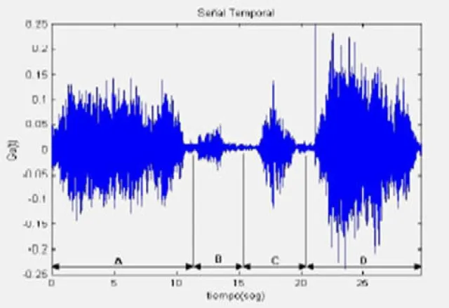
Healthy insulation has little leakage, so total current keeps falling for several minutes and apparent resistance keeps climbing. Wet or contaminated insulation is dominated by leakage: the reading flattens out early and at a low value. That behavior is the basis of every time-resistance test.
Spot test, PI and DAR
Spot test
Apply the voltage for a fixed time, usually one minute, and record IR1min. It is useful against a minimum value and, more importantly, against the same asset’s history — provided voltage, connection and temperature are comparable.
Polarization index (PI)
PI = IR10min / IR1min. Because it is a ratio of two readings on the same equipment at the same temperature, it is far less sensitive to temperature than a spot reading. IEEE 43 recommends minimum PI values of 1.5 for thermal class A insulation and 2.0 for classes B, F and H. It also notes that when IR1min corrected to 40 °C is above roughly 5,000 MΩ, PI may not be meaningful and should not be used alone to reject a machine.
Dielectric absorption ratio (DAR)
DAR uses two shorter readings, most commonly IR60s / IR30s. It is handy when there is no time for a 10-minute test, or on small, low-capacitance equipment where absorption finishes quickly. IEEE 43 does not set DAR limits; acceptance criteria come from instrument manufacturers or your plant’s own procedures, and DAR is best used as a trend.
Choosing the test voltage
For rotating machine windings, IEEE 43 bases the DC test voltage on the winding’s rated voltage:
| Winding rated voltage (V) | Suggested DC test voltage (V) |
|---|---|
| Below 1,000 | 500 |
| 1,000 – 2,500 | 500 – 1,000 |
| 2,501 – 5,000 | 1,000 – 2,500 |
| 5,001 – 12,000 | 2,500 – 5,000 |
| Above 12,000 | 5,000 – 10,000 |
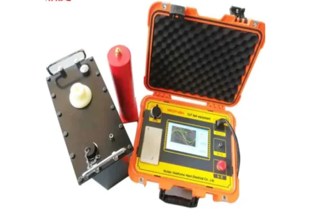
For cables and transformers, the voltage comes from the applicable standard, the manufacturer or the owner’s procedure. On aged medium-voltage XLPE cable, IEEE 400 discourages DC high-potential testing; the higher-stress assessment is done with VLF per IEEE 400.2, and IR stays as a low-voltage diagnostic. Whatever you choose, use the same voltage every time so the trend is valid.
Temperature correction
Insulation resistance drops roughly exponentially as temperature rises, which is why IEEE 43 asks for rotating-machine readings to be referred to 40 °C. The old rule of thumb — resistance halves for every 10 °C rise — is a reasonable first approximation, but the standard acknowledges it varies by insulation system. The more reliable approach is to measure the same machine at several temperatures and build its own curve, or at minimum record winding temperature (not ambient) and test under consistent conditions: always cold, or always right after shutdown. For transformers, use the manufacturer’s correction factors or those in IEEE C57.152.
Interpreting results by equipment type — and by trend
Motors and generators
IEEE 43 gives minimum IR1min values at 40 °C: 100 MΩ for most form-wound AC windings and DC armatures built after about 1970; 5 MΩ for random-wound machines and form-wound coils rated below 1 kV; and kV + 1 MΩ for older windings. A reading that still passes the minimum but has fallen sharply since the last test deserves investigation.
Cables
IR falls as length increases, so compare against previous readings on the same circuit or against per-kilometer normalized values. Test each phase against the other two phases and the shield, all grounded, and clean the terminations so surface leakage is not mistaken for insulation failure.
Transformers
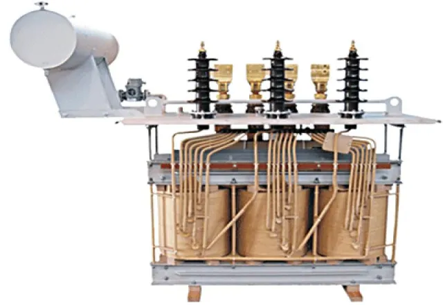
Measure high-to-low-and-ground, low-to-high-and-ground and high-to-low. Oil-filled transformers typically show lower PI values than rotating machines and should not be judged against motor limits; combine IR with power factor, oil analysis and turns ratio.
Reading the trend
A single reading tells you little. Plot corrected IR and PI at every outage, using the same instrument, voltage and connection. A steady decline points to progressive moisture or contamination; a sudden drop suggests damage or water ingress. A falling PI with stable IR can indicate surface contamination.
Field checklist
- Apply lockout/tagout, verify absence of voltage and ground the equipment before connecting. In Mexico, NOM-029-STPS-2011 from the Ministry of Labor (STPS) sets the safety requirements for electrical maintenance work.
- Disconnect VFDs, surge capacitors, arresters and any electronics that should not see the test voltage.
- Record winding temperature, relative humidity and cleanliness.
- Repeat the same voltage and connection as previous tests; use the guard terminal to remove surface leakage where appropriate.
- Take readings at 30 s, 1 min and 10 min to get spot, DAR and PI from one test.
- Discharge to ground afterward; IEEE 43 recommends grounding for at least four times the voltage application time.
- Correct to the reference temperature and log the result in the asset history.
High-voltage testing must be performed only by qualified personnel, with the equipment de-energized and under lockout/tagout.
FAQ
Does PI replace the spot reading?
No. They complement each other: the corrected spot reading shows the absolute insulation level, and PI describes the shape of the absorption curve. IEEE 43 evaluates both.
Can I test a motor while it is connected to its VFD?
It is not recommended. Disconnect the motor at its terminals; the test voltage can damage the drive electronics, and the reading would include the drive and cable.
How often should I test?
It depends on criticality, environment and history. Typical practice is to include it in every scheduled preventive maintenance, before energizing stored equipment and after any moisture event or fault.
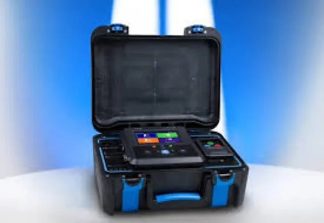
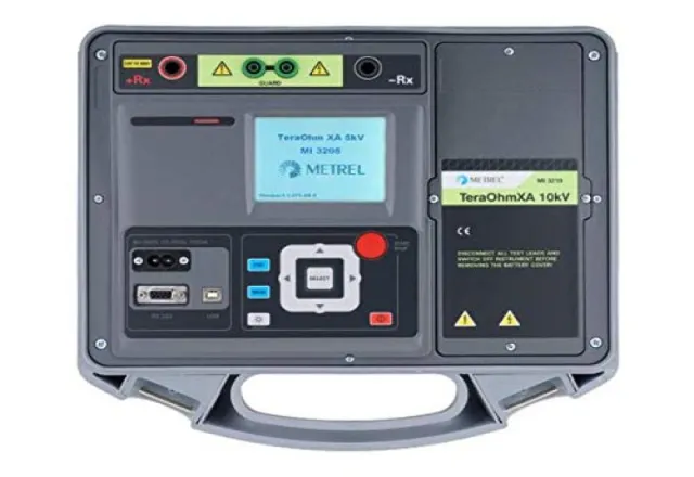
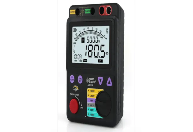
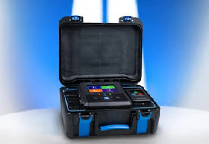
CreativeIT Group, an electrical test laboratory in Monterrey serving all of Mexico, performs insulation resistance testing on cables and windings on site or in our lab, documented with photos and video and, if you require it, witnessed by your team. We also offer Megger, hipot and VLF insulation testing, 10 kV insulation tester rental and insulation testers for sale, with NIST-traceable calibration. Our engineers do the analysis themselves and reply the same day: request a quote, call +52 (81) 4777 6921 or email info@creativeit.mx.