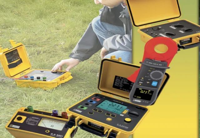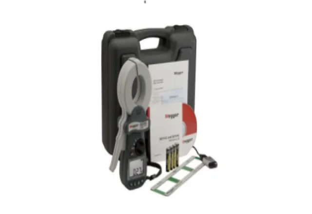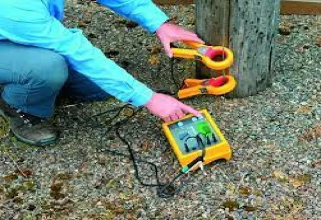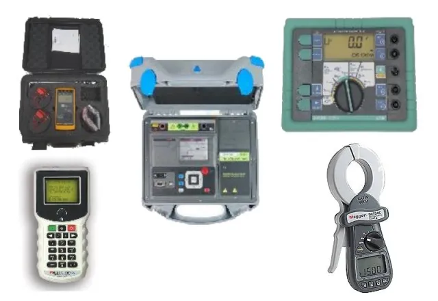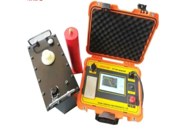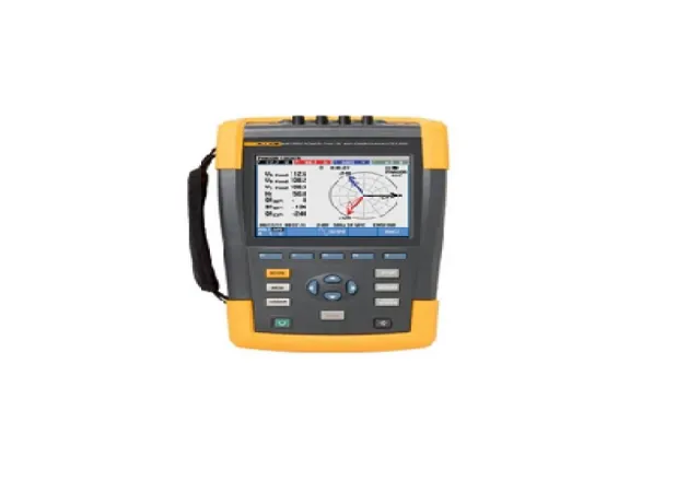
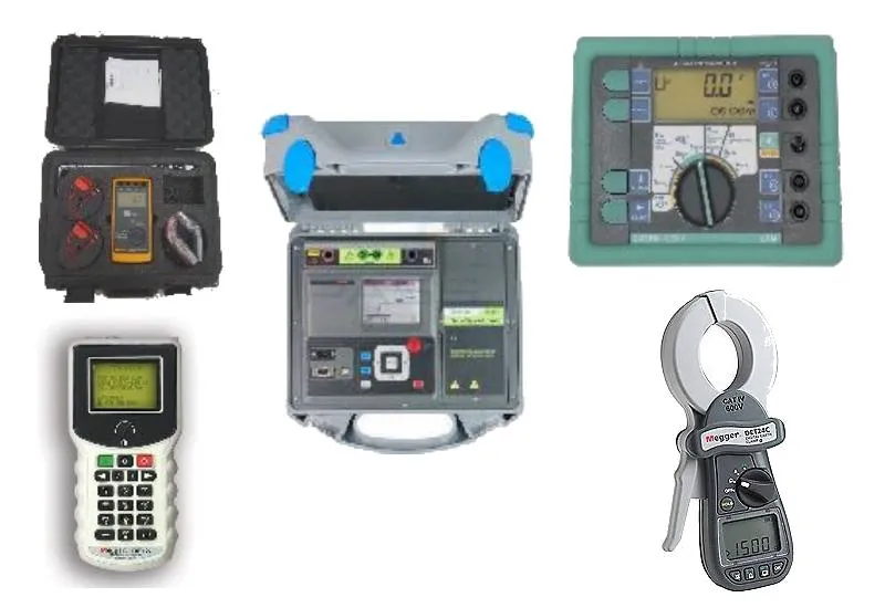
A grounding system that looks fine on the drawings may not perform in the field: corroded rods, loose connections, dry soil, or a plant expansion nobody tied into the grid. The only way to know is to measure. But the number on a test report depends heavily on which method was used and how. This guide walks through the common methods, when each applies, and what Mexico’s NOM-022-STPS-2015 and NOM-001-SEDE-2012 require — useful if you manage a plant in Mexico from a US, European or Asian headquarters.
Ground resistance vs soil resistivity
Ground (earth) resistance, in ohms, is the opposition an electrode or grid presents to current flowing into the earth. It’s what you verify during maintenance and what the codes regulate.
Soil resistivity, in ohm-meters, is a property of the soil itself. You measure it before designing or expanding a grounding system, because it drives how many rods you need, how long and how far apart. IEEE 81 is the reference guide for both measurements; substation grid design follows IEEE 80.
Fall-of-potential (3-pole)
The classic method. Current is injected between the electrode under test (E) and a remote current probe (C); a potential probe (P) is placed between them and the voltage is measured. Resistance is V/I.
- C must sit outside the influence zone of the system under test — several times its largest dimension away. For a single rod that’s tens of meters; for a large grid it can be hundreds.
- In uniform soil, the true value is read with P at roughly 62% of the E–C distance (the “62% rule”).
- To validate, move P forward and back (say, to 52% and 72%). If the readings agree, you’re on the plateau and the result is good. If not, C is too close.
You have to disconnect the electrode from the system (or use the selective method) so you’re not measuring parallel paths.
4-pole and selective methods
The 4-pole setup runs separate current and potential leads to the electrode under test, which removes test lead resistance from the reading. It’s the better choice when you expect low values — substation grids, multi-rod systems — or when you’re running long leads.
The selective method adds a current clamp around the electrode’s ground conductor to a fall-of-potential setup. The instrument sees only the current entering that electrode, so you can test it without disconnecting it from the rest of the system. It saves time and avoids leaving a facility ungrounded during the test.
Clamp-on (stakeless) method
A clamp-on tester induces a voltage on the ground conductor and measures the resulting current. It’s fast and needs no auxiliary stakes, but it comes with firm conditions:
- It only works if there’s a loop: the electrode must be in parallel with other electrodes through the earth — utility poles on a multi-grounded neutral, or several bonded rods.
- The reading is the whole loop: the electrode under test in series with all the others in parallel. With many parallel paths, that approaches the electrode’s own resistance.
- It doesn’t work on an isolated rod or a single grid. If the loop closes through metal — a cable shield, building steel — you’ll get a misleadingly low number.
Great for routine checks on many points and for finding open bonds; it does not replace fall-of-potential for commissioning a new system.
Soil resistivity: the Wenner method
Four probes are driven in a straight line at equal spacing a. Current is injected through the outer pair and voltage measured across the inner pair. With probe depth small compared to a, apparent resistivity is ρ = 2πaR.
- Repeat at several spacings — wider spacings reflect deeper soil layers.
- Take at least two perpendicular traverses to catch non-uniform soil.
- Stay clear of buried pipes, metal fences and conductors running parallel to the traverse.
The data feeds a soil model (two-layer, for example) used in grid design.
What Mexican regulations require
NOM-022-STPS-2015
NOMs are Mexico’s mandatory federal standards; this one is issued by STPS, the federal labor ministry, and is enforced through workplace inspections. It applies where flammable or explosive substances are stored, handled or transported, and where processes can generate or build up static charge. It requires grounding and, where applicable, lightning protection, and it requires measuring grounding network resistance and bonding continuity at least every 12 months, with records kept. The standard sets reference maximums of 25 Ω for the grounding network and 10 Ω for the lightning protection system.
NOM-001-SEDE-2012
Mexico’s electrical installations code, closely modeled on the US NEC and verified by licensed inspectors known as UVIEs. Article 250 covers grounding and bonding. As in the NEC, a single rod, pipe or plate electrode that does not measure 25 Ω or less must be supplemented by an additional electrode. Substations and other cases carry their own requirements; check the edition in force and your inspector’s criteria.
Method selection checklist
| Situation | Recommended method |
|---|---|
| Single rod or small system, commissioning or troubleshooting | Fall-of-potential (3-pole) with plateau check |
| Substation grid or low expected values | 4-pole, long leads, plateau check |
| Testing without disconnecting the electrode | Selective (stakes + clamp) |
| Many points on a multi-grounded system | Stakeless clamp |
| Designing or expanding the system | Wenner resistivity at multiple spacings and directions |
- Calibrated instrument with a current certificate.
- Sketch showing auxiliary probe locations and distances.
- Soil and weather conditions recorded.
- Qualified personnel, lockout/tagout, and a current check on the ground conductor before disconnecting it.
FAQ
How often should ground resistance be measured?
If your site falls under NOM-022-STPS-2015, at least every 12 months. Outside that scope, annual testing is common practice, plus after modifications, expansions or lightning strikes.
Why did my reading change between the rainy and dry seasons?
Soil resistivity depends strongly on moisture and temperature. Many engineers prefer to test in the dry season because it represents the worst case.
Can I use only a clamp-on tester to comply?
It depends on the system. On an isolated rod or a single grid, a clamp won’t give a valid reading. Choose the method to fit the configuration and document it in the report.
CreativeIT Group performs ground resistance and lightning protection testing across Mexico, NOM-022-STPS ground resistance testing, and soil resistivity and ground resistance studies for design. If your own team prefers to do the work, we rent instruments such as the Megger DET24C clamp-on ground tester. Our instruments are traceable to NIST and every test is documented with photos. Get in touch — we reply the same day.