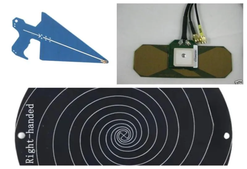
An antenna doesn’t just detect signals; it reveals what is really happening in your electromagnetic environment.
Log-Periodic Antenna
The 0.6–10 GHz Log-Periodic Antenna is an electromagnetic pickup instrument designed to cover an extremely wide range of the radio-frequency spectrum. It is not simply a “receiving” antenna; it is a calibrated sensor used in laboratory, industrial field and regulatory testing environments to convert radiated electromagnetic energy into electrical signals that a spectrum analyzer can quantify.
In physical terms, what this antenna does is intercept the electric and magnetic field of an electromagnetic wave propagating through space, induce a proportional current in its metallic elements, and transfer that energy to a 50-ohm transmission line, normally a coaxial cable, which carries it to the measuring instrument. The spectrum analyzer turns that signal into a graphical representation of amplitude versus frequency, making it possible to observe the spectral behavior of the emitting source.
What sets the log-periodic antenna apart from other antennas is its geometric architecture. It consists of multiple dipoles of different lengths arranged in a staggered fashion following a logarithmic progression. Each set of elements is electromagnetically activated in a specific region of the spectrum, which allows the antenna to maintain a relatively stable impedance and a consistent directional response across the entire 600 MHz to 10 GHz range. It does not work as a single-frequency resonant antenna, but as a self-scaling structure that adapts its active zone to the incident frequency.
When used with spectrum analyzers from manufacturers such as Keysight Technologies, Rohde & Schwarz, Tektronix or Anritsu, the antenna enables radiated emissions measurements, electromagnetic interference analysis and RF behavior diagnostics in electronic equipment, industrial systems and telecommunications devices.
Practical use begins with connection through a low-loss coaxial cable. The spectrum analyzer is then configured by setting the desired frequency range, resolution bandwidth, reference level and detection parameters. The antenna must be placed in a carefully defined position, since the measurement depends on geometric factors such as distance, height, polarization and orientation relative to the emitting source. In regulatory environments, these conditions are standardized and must be reproduced precisely to ensure repeatability and metrological traceability.
In electromagnetic compatibility testing, the antenna is used when a manufacturer needs to verify that its equipment does not exceed the emission limits set by regulatory bodies such as IEC, CISPR, IEEE or FCC. In these scenarios, the equipment under test is placed in an anechoic chamber or on an open area test site, and the antenna is moved to different heights and polarizations to detect the point of maximum emission. The goal is to identify harmonics, spurious emissions, RF leakage or unwanted interference that could affect other nearby devices.
In the telecommunications sector, this antenna makes it possible to analyze WiFi signals at 2.4 GHz and 5 GHz, evaluate microwave links, study LTE and 5G sub-6 GHz behavior, verify effective radiated power and diagnose interference between systems. In these cases, the antenna not only detects the presence of a signal but also allows evaluation of spectral stability, occupied bandwidth, and the presence of spurious signals and distortion.
In industrial environments, especially in electrical substations, manufacturing plants and data centers, the log-periodic antenna can be used to identify sources of electromagnetic noise that affect control systems, industrial communications or sensitive equipment. Variable frequency drives, power electronic converters, welding systems or switching power supplies can generate emissions that interfere with sensors or wireless networks. The antenna makes it possible to locate these emissions and quantify their intensity.
In research and development, this tool is essential during the design phase of new electronic products. Before sending a device for official certification, engineers perform radiated emissions pre-compliance tests to detect design problems in shielding, PCB traces or filtering. The antenna provides early feedback that reduces redesign costs and failures at the accredited laboratory.
The reason a log-periodic antenna is used specifically in the 0.6–10 GHz range is that this segment of the spectrum concentrates most modern wireless communication technologies and high-speed digital electronic devices. Fast signal transitions, internal oscillators and radio modules generate harmonic components that can extend several gigahertz above the fundamental frequency. A narrowband antenna would be insufficient to capture the entire spectrum of interest.
In the field, it can also be used for electromagnetic environment studies, identification of unknown RF sources, spectrum monitoring in critical facilities and evaluation of electromagnetic exposure. Its directional nature allows it to be pointed toward the possible emitting source and improves the signal-to-noise ratio compared with omnidirectional antennas.
From a construction standpoint, these antennas are usually made of aluminum or lightweight conductive materials, with a rigid structure to maintain precise geometric alignment. Mechanical stability is crucial because small variations in element position can alter the frequency response.
High-Gain Spiral Antenna
The High-Gain Spiral Antenna with VSWR below 2.4 is an electromagnetic pickup device designed to operate over a wide bandwidth with circular polarization and impedance stability in high-frequency applications. Its spiral geometry allows it to maintain relatively constant electrical characteristics over a broad spectral range, making it a highly specialized tool for complex signal analysis, spectrum studies, advanced EMC testing and critical telecommunications applications.
Physically, this antenna is made up of two conductive arms wound in a symmetrical spiral. The electromagnetic principle governing its operation is that of the progressive active region. This means that the entire structure does not radiate or receive simultaneously at all frequencies; different sections of the spiral become active depending on the incident wavelength. As the frequency increases, the active region shifts toward the center of the spiral. As the frequency decreases, the active region moves outward. This behavior allows the antenna to maintain a broad, relatively uniform response without needing to resonate at one specific frequency.
One of the most important characteristics of this type of antenna is a VSWR below 2.4. The Voltage Standing Wave Ratio is a direct indicator of the level of matching between the antenna and the transmission line, normally 50 ohms. A value below 2.4 means that the power reflected back toward the measuring equipment is limited and that most of the captured energy is transferred efficiently to the system. In practical terms, this reduces measurement errors, avoids excessive losses and protects the input stage of the spectrum analyzer. In professional measurement systems, maintaining a controlled VSWR is essential to ensure metrological accuracy and repeatability.
When this antenna is connected to spectrum analyzers from manufacturers such as Keysight Technologies, Rohde & Schwarz, Anritsu or Tektronix, its function is to act as an electromagnetic transducer. It intercepts the electric and magnetic field of a wave propagating through space, induces a proportional current in its conductive arms and delivers that signal to the instrument for frequency-domain analysis. The result is a graphical representation of amplitude versus frequency that makes it possible to identify emissions, harmonics, interference and complex spectral behavior.
A fundamental difference from log-periodic antennas or conventional dipoles is circular polarization. Instead of picking up only signals with a specific electric field orientation, the spiral antenna responds to rotating signals. This means it can receive energy regardless of the angular orientation of the transmitter, which is crucial when the emitting source is moving, when there is relative rotation between transmitter and receiver, or when the signal undergoes multiple reflections that alter its original polarization. In real environments, especially industrial or urban indoor settings, reflections off metal surfaces generate mixed-polarization components. The spiral antenna reduces dependence on precise mechanical alignment and improves measurement consistency.
In advanced electromagnetic compatibility applications, this antenna is used when wideband pickup with stable behavior under orientation variations is required. It can be used for studies of complex emissions where the sources are not stationary or when analyzing the behavior of wireless devices under real conditions. It is also useful in research and development, where RF system prototypes are evaluated and their performance needs to be analyzed in multiple polarization scenarios.
In spectrum monitoring and interference analysis, the spiral antenna can detect transmissions whose orientation is unknown or variable. This includes wireless systems, microwave links, experimental signals and electromagnetic environment studies.
The high gain in this type of antenna is achieved through structural design and, in many cases, the addition of rear cavities or reflectors that concentrate energy toward the main axis. This improves directivity and increases the signal-to-noise ratio during measurement. Higher gain means weak signals can be detected more clearly, which is critical in low-level emissions analysis or sensitivity testing.
In industrial environments, the spiral antenna can be used to analyze emissions from power electronic systems, frequency converters, industrial wireless transmitters and high-frequency communication equipment. In specialized laboratories, it is also used for materials characterization, electromagnetic absorption studies and scientific research testing.
Combined GPS/GSM/3G Antenna
The combined GPS/GSM/3G antenna represents an integrated technological solution that responds to the growing need to have multiple communication services in a single physical device. This type of antenna, designed to operate simultaneously in the satellite positioning and mobile telephony bands, is a fundamental element in telemetry applications, fleet tracking, alarm systems with cellular communication, state-of-the-art IoT devices and advanced mobile terminals. The complexity of its design lies in the need to maintain optimal performance in very disparate frequency bands, ranging from the relatively low frequency of 850 MHz up to the 2100 MHz of 3G, passing through the specific GPS band at 1575 MHz, all with port-to-port isolation levels that prevent mutual interference and preserve the sensitivity of the satellite receiver.
The operation of a combined GPS/GSM/3G antenna is based on the use of multiple radiating elements arranged in a small space, optimized through electromagnetic coupling techniques and carefully designed matching networks. The most common arrangement uses a main radiating element for the telephony bands, usually a monopole or a patch of complex geometry capable of resonating at multiple frequencies, and a separate element for GPS, generally a high-permittivity ceramic patch that drastically reduces the physical size of the radiator for the 1575 MHz frequency.
The most notable feature of these antennas is their ability to provide a practically hemispherical radiation pattern in the GPS band, necessary to receive signals from satellites distributed across the entire sky, while for the GSM and 3G bands an omnidirectional pattern in the horizontal plane is sought, ensuring communication with base stations located in any direction around the vehicle or device. This dual requirement is resolved through the geometric arrangement of the elements and, in many cases, by including a ground plane that acts as a reflector and helps shape the radiation patterns.
The GPS element consists of a radiating patch made of ceramic materials with a high dielectric constant, typically between 20 and 40, which allows the physical length of the patch to be much smaller than the free-space wavelength. This patch is fed by a probe or by proximity coupling, and usually incorporates a preamplifier stage integrated into the antenna housing itself, since signals from GPS satellites reach the Earth’s surface at extremely low power levels, on the order of -130 dBm, and any loss in the downstream cabling would irreversibly degrade the signal-to-noise ratio.
To understand the complexity of this antenna, it is necessary to examine in detail the frequency bands it must cover and the services operating in them. In the case of GPS, we find the L1 carrier centered at 1575.42 MHz, with a bandwidth of approximately 20 MHz that carries the civilian C/A code signals and other modulations restricted to military or authorized uses. Receiving these signals requires an antenna with moderate gain, typically between 3 and 5 dBic, and right-hand circular polarization, which is the polarization used by the satellites to minimize the effects of Faraday rotation in the ionosphere and reflections off the Earth’s surface.
In mobile telephony, GSM bands mainly comprise those at 850 MHz and 900 MHz, as well as 1800 MHz and 1900 MHz, although the GSM name is more closely associated with the former. For 3G, the most widespread bands are 2100 MHz in Europe and much of Asia, and 1700/2100 MHz in the Americas, along with other regional variants. A quality combined antenna must show acceptable response in all of these bands, with a standing wave ratio below 2.5 and a radiation efficiency that does not compromise link quality, especially in marginal coverage conditions where every tenth of a decibel counts.
The outer housing protects the elements from the weather and provides a means of attachment to the vehicle or structure. The most commonly used materials are plastics with high UV resistance, such as ABS or polycarbonate, with additives that prevent yellowing and degradation from prolonged sun exposure. Watertightness is achieved with rubber or silicone gaskets, and many models include a magnet in the base for magnetic mounting on metal surfaces, a very common solution in fleet and rental vehicle applications.
One of the most critical aspects in the design of these combined antennas is the inclusion of the low-noise amplifier for the GPS signal. Since the received signal level is extremely weak, any loss in the coaxial cable connecting the antenna to the receiver would degrade system sensitivity unacceptably. For this reason, the amplifier is placed as close as possible to the radiating element, in many cases integrated on the same printed circuit board that supports the ceramic patch.
The amplifier is powered through the same coaxial cable that carries the signal, using a technique known as phantom power (bias tee). A DC voltage, typically 3.3 or 5 volts, is injected into the cable from the receiver and reaches the amplifier through a low-pass filter that separates the DC from the radio frequency. This arrangement eliminates the need for an additional cable and greatly simplifies installation.
Need Advice or a Quote?
Contact us today on WhatsApp at 8117860768 for pricing, availability and usage recommendations. At Creativeit Group, our specialized technical team can help you integrate it into your measurement processes.