Introduction
Modern communication devices—mobile phones, RF modules, radios, IoT systems—do not draw power uniformly. Their operation is organized in bursts: brief periods of high activity, associated with signal transmission or activation of power amplifiers, followed by idle intervals in which consumption drops dramatically. The result is a current that does not flow continuously but in high-amplitude, short-duration pulses, often on the order of microseconds.
This behavior imposes a demand that goes beyond accuracy under steady-state conditions: the power supply must be able to hold the voltage stable precisely when demand changes the most. In these systems, power quality is measured by dynamic response, not by DC accuracy.
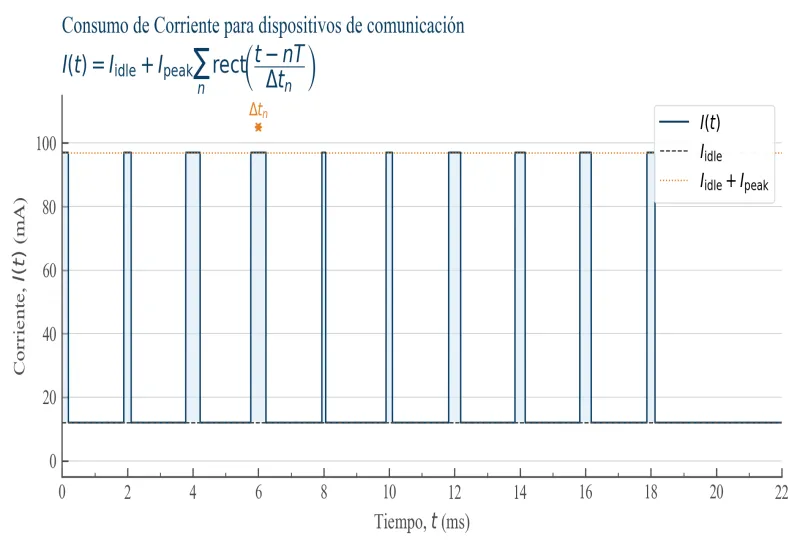
Representative current pulse train of a communications device. Note how short the pulse width is relative to the idle periods. In many cases, the pulse duration is shorter than the control loop response time of a conventional regulated power supply.
Passive behavior of a battery
An electrochemical battery, such as a lithium-ion cell, can be described as a passive system whose response is governed by internal physical properties. Its simplest model includes an open-circuit voltage source and an internal resistance.
This relationship means that any change in current is immediately reflected in the output voltage. There is no delay associated with control decisions; the response is determined directly by the physics of the system.
However, a real battery exhibits a frequency-dependent impedance. At low frequencies, electrochemical and diffusion processes dominate, which increases impedance and produces slower behavior. In an intermediate range, dynamics associated with equivalent RC elements appear, introducing phase shifts and capacitive effects. At high frequencies, the response tends to be dominated by the internal resistance and by the inductive parasitics of the connections, maintaining a relatively low and stable impedance compared with other systems.
It is important to note that, although complex effects may appear, the battery remains a passive system. This means its response to disturbances is smooth, monotonic, and free of overshoot or artificial delays. There is no active mechanism that “corrects” the voltage; it simply responds according to its impedance.
Behavior of a regulated power supply
By contrast, a regulated power supply introduces a fundamental element: a control loop that continuously adjusts the output voltage to hold it at a target value. This mechanism involves sensing, processing, and correction, which necessarily introduces a characteristic response time.
At low frequencies, where load variations are slow, the supply can regulate the voltage effectively, presenting a very low impedance. However, as the frequency of the disturbances increases, the loop loses its ability to react and the effective impedance begins to rise.
This behavior has a critical consequence with pulsed loads. If the duration of the current pulse is shorter than the system’s response time, the supply cannot correct the voltage during the event. In that case, the response is dominated by the output capacitor and other passive elements, producing a voltage drop that does not correspond to a constant physical impedance but to a dynamic limitation of the system.
In practical terms, this means that the supply’s impedance is not fixed but depends on the spectral content of the load. Fast pulses “see” a supply with higher impedance than slow pulses, which introduces a temporal distortion that does not exist in a real battery.
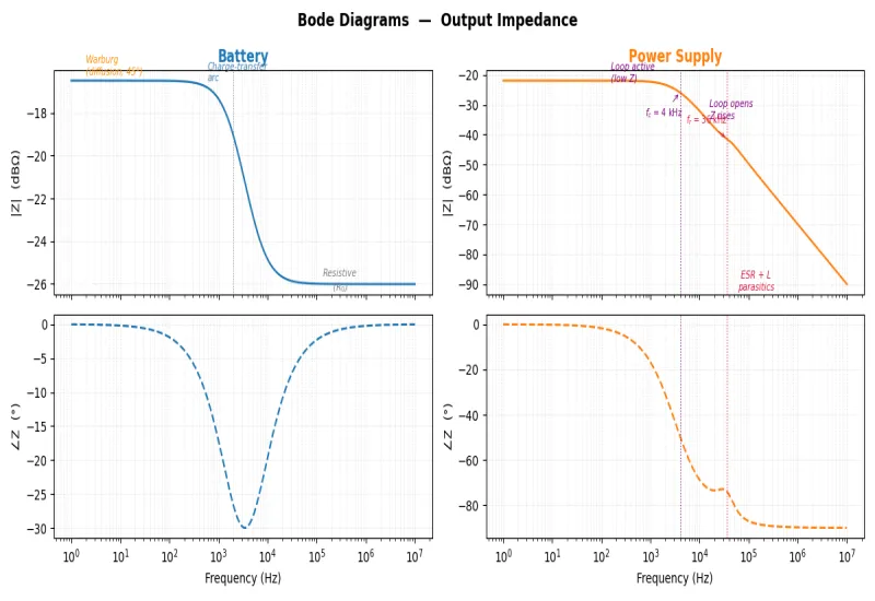
Bode plots of output impedance. The battery (blue) shows a low, stable impedance in the frequency band relevant to pulsed loads. The conventional regulated supply (orange) shows a marked rise in impedance above the control loop’s crossover frequency, as well as a resonant peak associated with the LC output filter. This peak is the origin of the ripple and noise that can be observed on the supply voltage of a real device.
Importance of suitable power supplies for communication devices
Given the nature of the loads in communication systems, the choice of power supply plays a critical role both for the integrity of the equipment and for the validity of the tests. An unsuitable supply can cause voltage drops that lead to resets, operating failures, or degraded RF performance. Even when the system does not fail, a supply that does not correctly reproduce real conditions can lead to wrong conclusions about energy consumption or design robustness.
In the most demanding scenario, the goal is for the supply not only to power the device but to faithfully reproduce the behavior of a battery. This requires not only a low base impedance but also a sufficiently fast response and, in some cases, the ability to model a specific impedance. The objective is for the device to “perceive” the same electrical dynamics it would have under real operating conditions.
Parameters that quantify dynamic behavior
Power supply datasheets include several parameters for evaluating these properties, although not always directly.
DC readback accuracy describes how faithfully voltage and current can be measured under steady-state conditions. This parameter is essential for characterizing consumption, but it provides no information about transient response.
More relevant for dynamic loads are the voltage drop on load changes and the transient response time. The former indicates the magnitude of the voltage deviation when a current pulse occurs, while the latter reflects how quickly the supply recovers to the nominal value. Both parameters are directly related to the effective impedance and to the bandwidth of the control loop.
Finally, current ranges and their associated specifications are fundamental in systems where very low consumption coexists with high peaks. The ability to measure and supply current accurately across several orders of magnitude makes it possible to properly capture the real dynamics of the device.
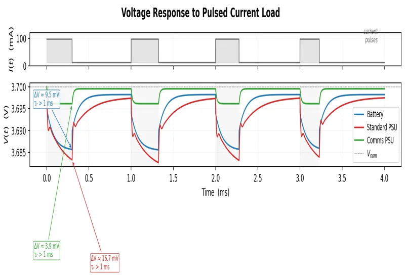
Voltage response of three systems to the same current pulse train. The battery (blue) produces a moderate drop and a smooth recovery, with no oscillations. The conventional supply (red) shows a larger drop and a prolonged transient with visible ripple, the result of a slow control loop and the resonance of the output filter. The specialized communications supply (green) shows the smallest drop and the fastest recovery of the three, with practically no ripple, thanks to its higher control bandwidth and low output impedance. The ΔV and τᵣ annotations on the first pulse quantify these differences.
Conclusion
Analyzing power supplies for communication devices requires going beyond DC accuracy. The key is to understand the interaction between the pulsed load and the supply’s dynamic impedance. While a battery responds immediately and passively, a regulated supply is limited by its control loop, which introduces delays and frequency-dependent impedance variations.
For this reason, a suitable supply for these environments must combine a low base impedance, a fast response, and controlled dynamic behavior. Only then is it possible to ensure both safe operation of the equipment and a realistic emulation of the conditions under which these devices were designed to operate.
We offer power supply rental for communication devices throughout Mexico; contact us on WhatsApp for more information.